![]()

YouTube


YOU'RE IN GOOD HANDS WITH OELTECHNIK
Products
The most important element of the product range is the heat transfer apparatus. In this, heat transfer of running fluids, gases or vapours is made possible in the direction of the temperature drop.
In addition to these individual units, OELTECHNIK also supplies complete oil supply and condensation units. Finally, the production program also includes various industrial filter units and pressure vessels for various applications.
The main product range consists of solutions that optimal fit to the customers` requirements. Therefore OELTECHNIK tends to productivity, efficiency and long product life of the aggregates, components and units for our customers in order to achieve long lasting business relations.
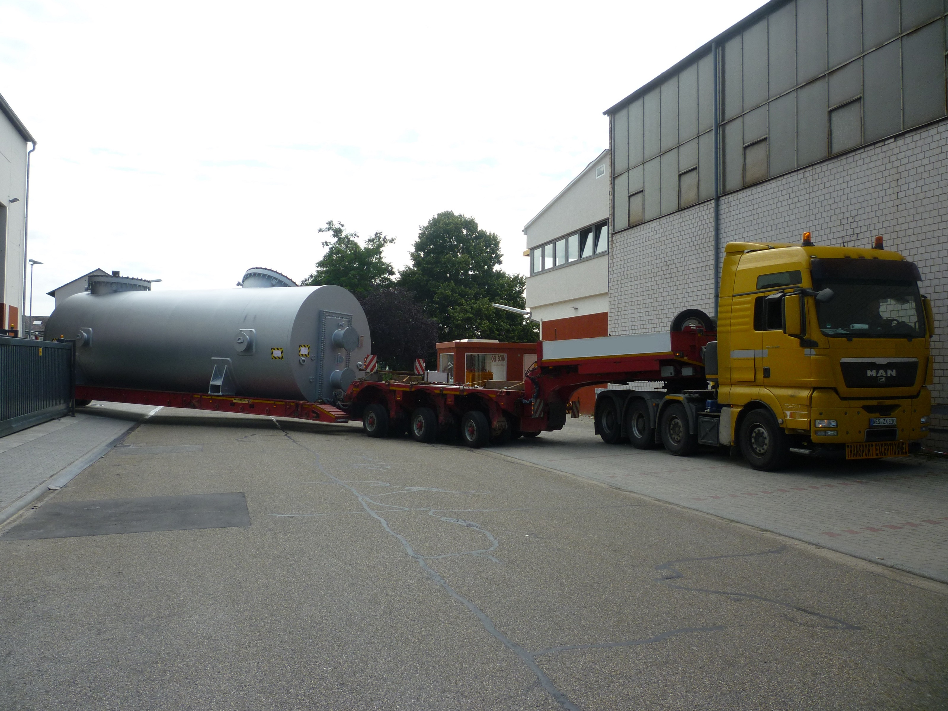
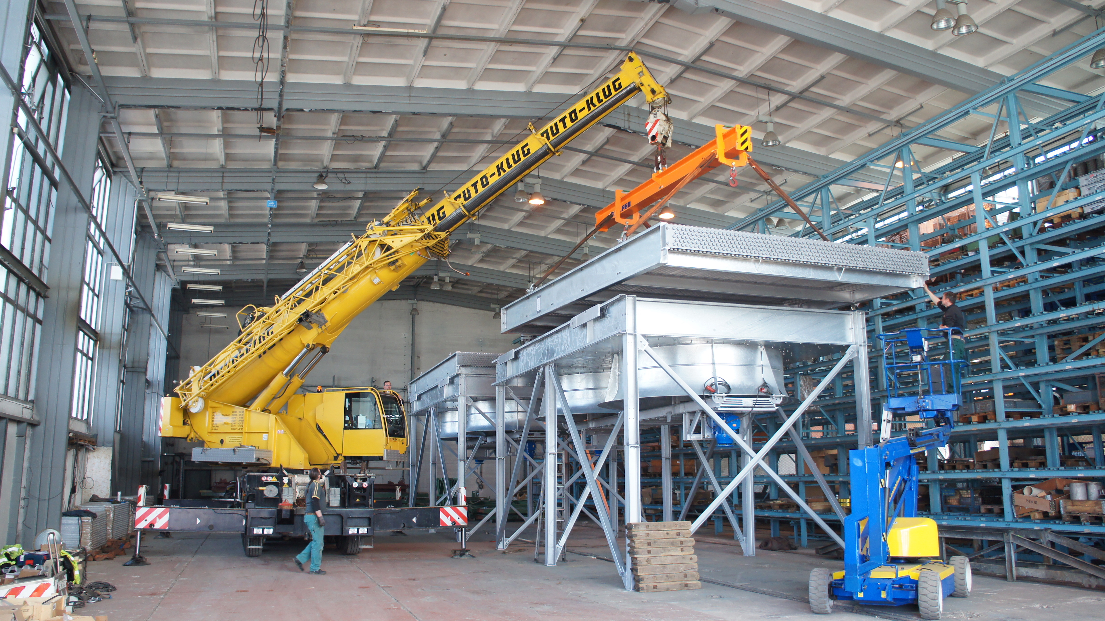
The production facilities are equipped with the most modern technology and enable the manufacture of single pieces weighing up to 100 tonnes and with a diameter up to about 4 meters. The well-proven logistical system and spare parts service guarantees a high degree of operational readiness for all OELTECHNIK products throughout the world.
"Made in Germany"
Products
Oil systems
Design parameters
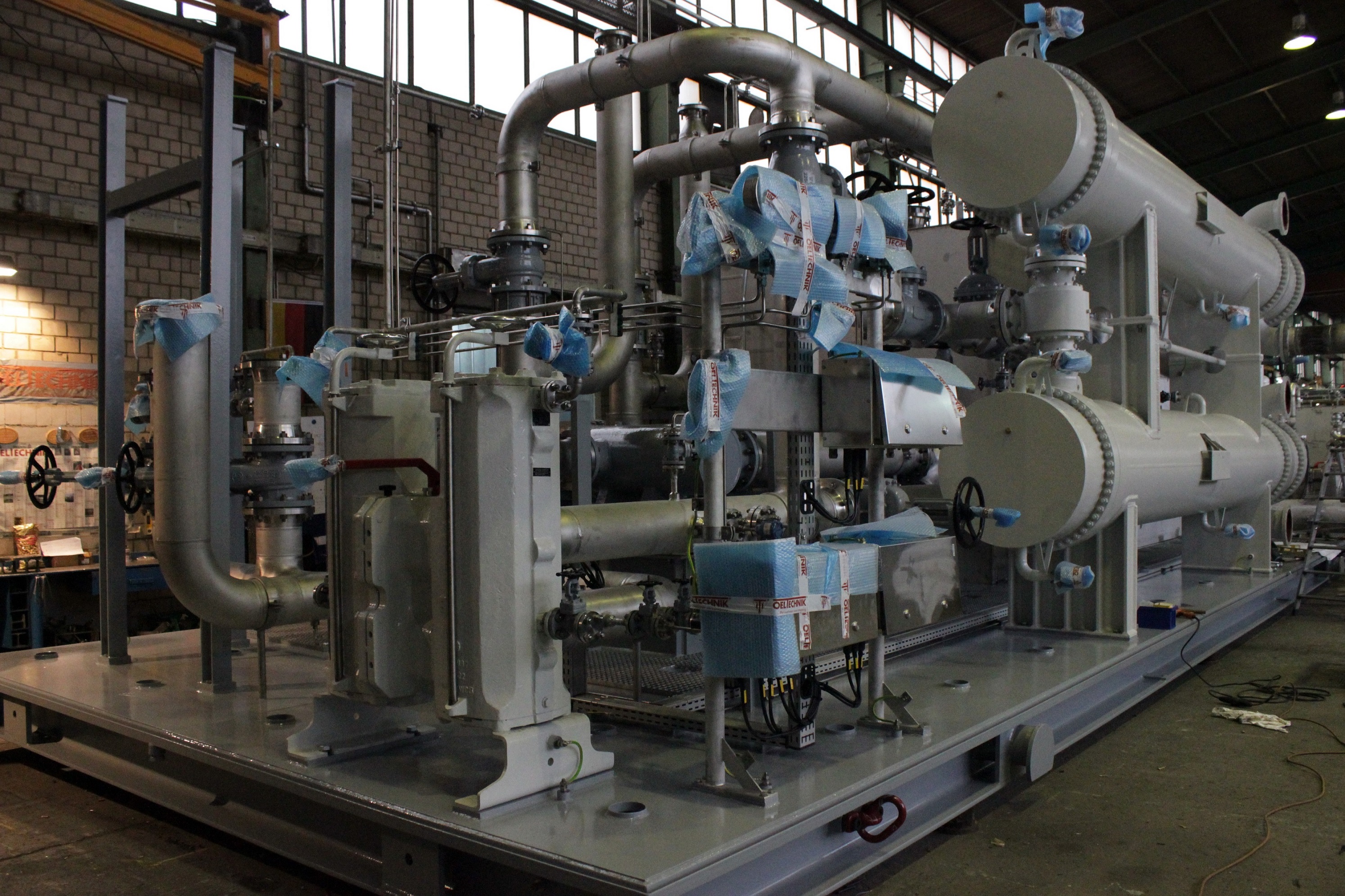
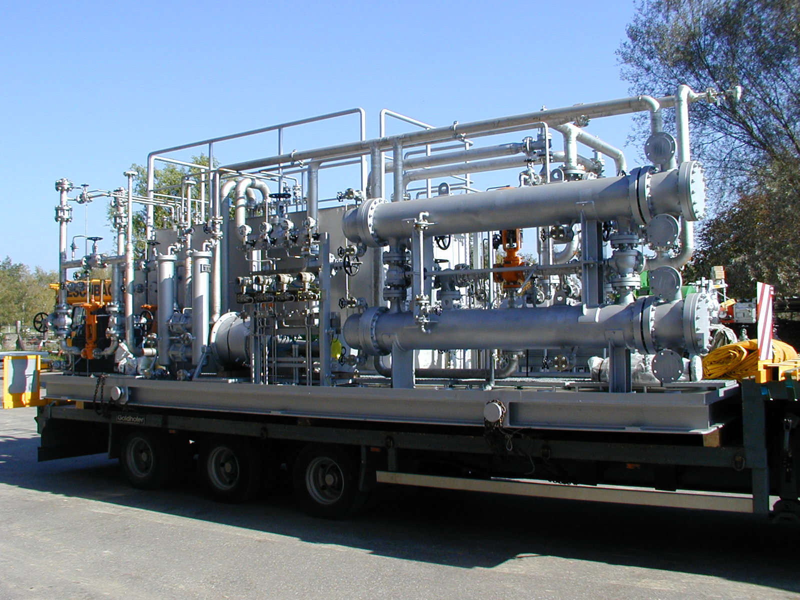
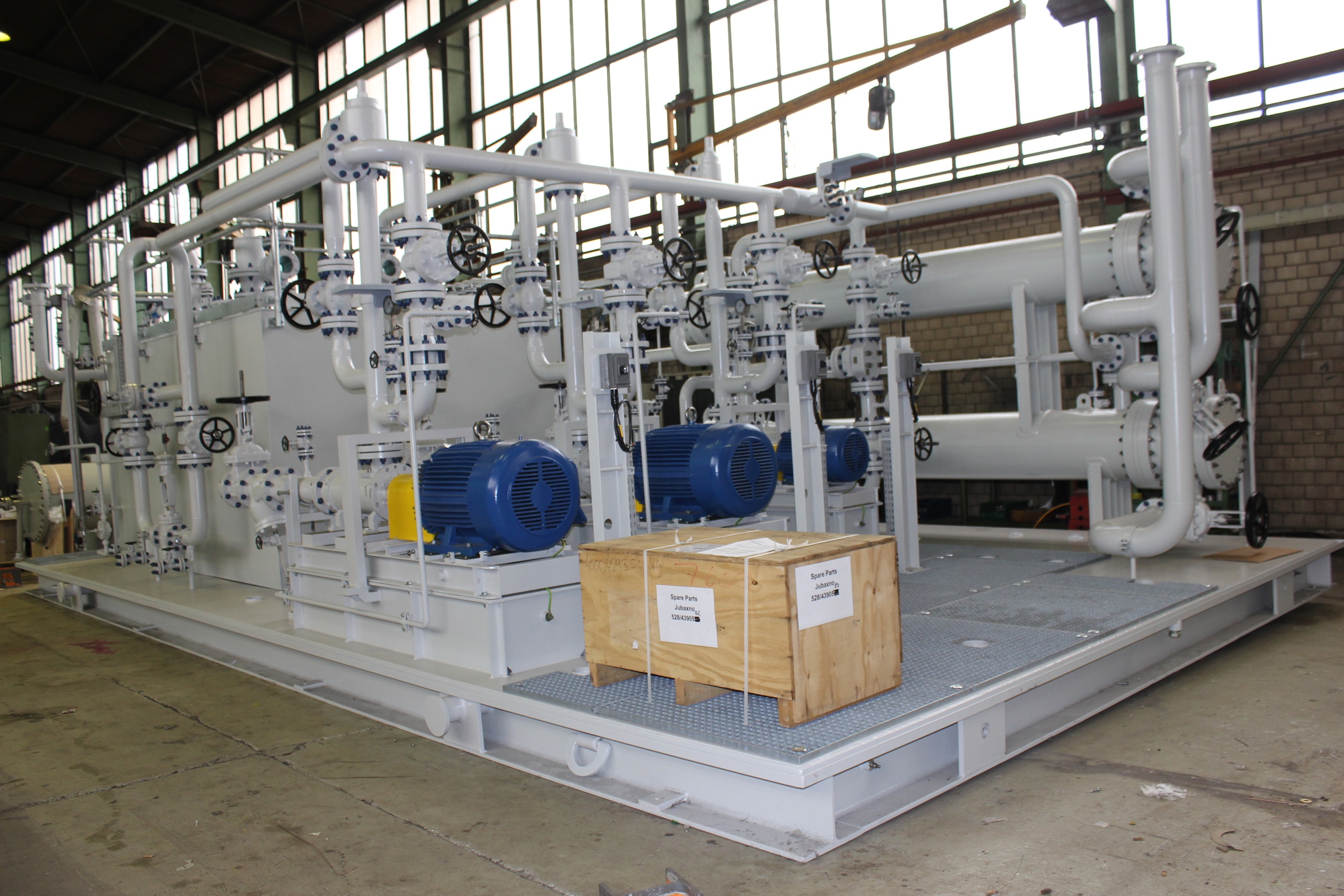
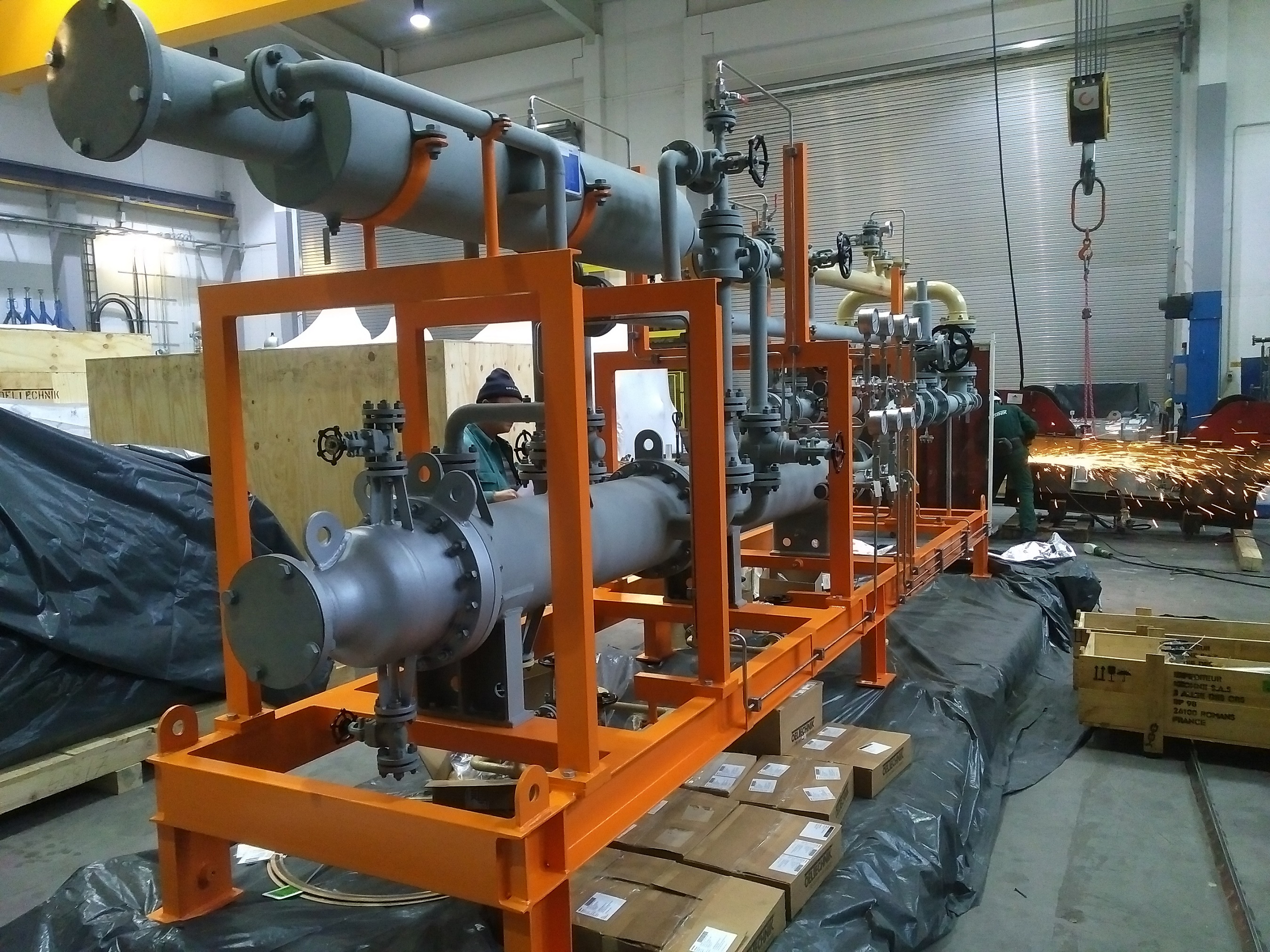
For over 50 years, OELTECHNIK oil supply units have been supplied as so-called compact units. The delivery program ranges from modular standard units to special lubricant, sealant and standard oil units and water injection units. These are used mainly in process compressors in industrial use.
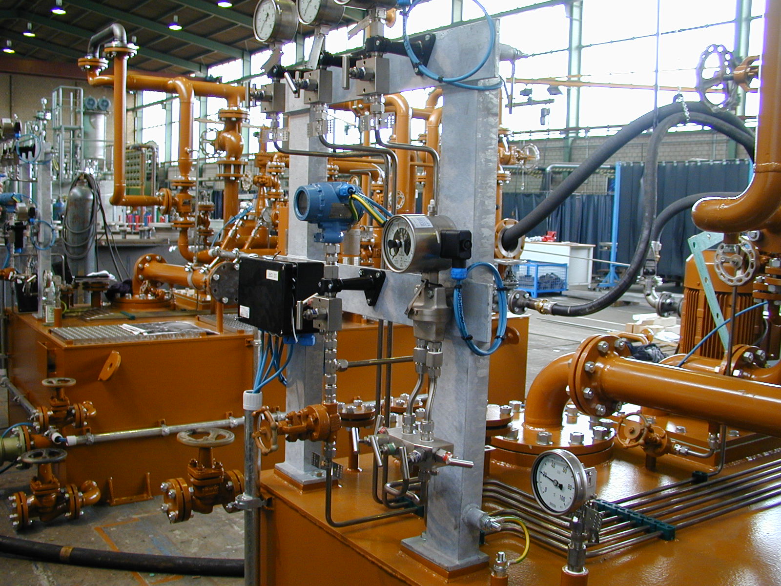
OELTECHNIK supplies complete engineering in accordance with the customer’s requirements. This means that the units are fitted out with both appropriate process technology and measurement and control technology.
If required, international regulations of the petrochemical industry or the standards of the American Petrol Institute (API) can be taken into account during construction. Basically, all units are designed to operate in continuous service and guarantee an enormously long service life.
OELTECHNIK has designed, engineered, tested and continuously improved its oil system product in response to the needs of the turbo machinery equipment manufacture. In-house testing facilities allow customers to witness oil system tests according to API 614 and other customers' specified requirements. OELTECHNIK's oil consoles are special engineered systems designed to perform an exceptional job in:
- Controlled oil cooling
- Filtering of all abrasives from bearings and other sources
- Degassing the oil coming into the system
OELTECHNIK has supplied lube, seal and control oil system to the international market for over 35 years. Oil systems designed and manufactured in accordance to API Standard 614 are a daily routine.
OELTECHNIK's oil systems are in use worldwide. Our design and manufacturing capabilities cover all international design codes and national regulations. As oil coolers, filters, accumulators, and occasionally also oil reservoirs are considered pressure vessels, they have to be built according to codes and regulations of the country of installation. With us you can establish a world wide standard of your product since we have the knowledge, capability and certified authority to build pressure vessels to all international design codes and national regulations.
Typical applications:
- Compressors systems
- Off gas expander
- Lube oil systems for process pumps
- Steam turbines
- Gas turbines
Capabilities / Range of application:
|
Maximum flow rate for lube oil systems: |
bis 3600 l/min |
bis 952 GPM |
|
Design pressure: |
30 bar |
435 psi |
|
Maximum flow rate for seal oil systems: |
bis 250 l/min |
bis 66 GPM |
|
Design pressure: |
150 bar |
2176 psi |
Material of construction:
|
Reservoir, Piping: |
Stainless steel, Carbon steel |
|
Pumps: |
Carbon steel |
|
Instrumentation: |
Stainless steel |
|
Filter: |
Stainless steel, Carbon steel |
|
Accumulator: |
Stainless steel, Carbon steel |
|
Oil cooler: |
Carbon steel, Stainless steel shell; tubes according to water quality |
References

Element coolers
Design parameters
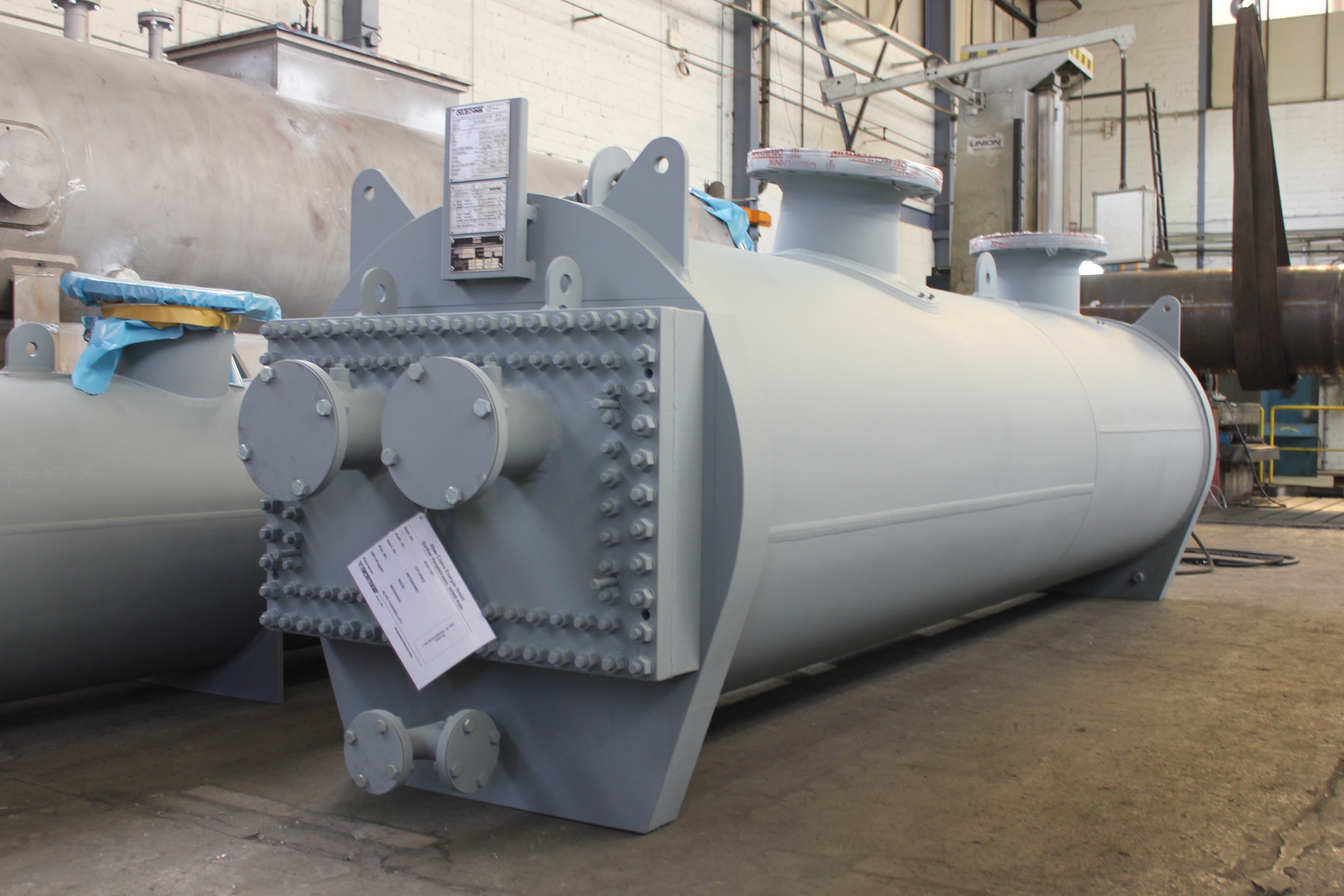
OELTECHNIK has developed, tested and continuously improved the EKE Element Intercooler product program in response to the need of the compressor industry. Over decades the in-house developed software has been checked against test performance of our equipment.
OELTECHNIK has always taken challenges to extend the applications of the EKE Element Intercooler to serve our innovative customers' requirements. OELTECHNIK's products are successfully in use worldwide. Our design and fabrication capabilities are all international design codes and national regulations.
The EKE Element Intercooler with enhanced surface finds its application where heat has to be transferred from a poor heat conducting fluid (e.g. gas) to a liquid fluid or vice versa. The liquid fluid is placed on the tube side, and the gaseous fluid is on the shell.
The EKE type heat exchanger allows with its enhanced outside tube surface to compensate the poor thermal conductivity of the gas. The gas flow is directed in one pass perpendicular through the enhanced tube bundle.
Even numbers of passes on the tube side are forming a combination cross-flow and counter-flow which allow for temperature approach of 5K.
Capabilities – Range of application:
| Design pressure: | 2-90 barg | 29-1305 psig |
| Design temperature: | -25 - 200 °C | -13 - 392 °F |
| Minimum flow rate: | ~7000 Nm3/h | ~4120 scfm |
| Maximum flow rate: | Function of operating pressure and allowable pressure drop | |
| Minimum shell diameter: | 560 mm | 22 inch |
| Maximum shell diameter: | ~3500 mm | ~138 inch |
Typical fluids :
| Shell side: | Wet air, dry air, Nitrogen, Oxygen, NH3, CO2, CO, CH4 and others |
| Tube side: | Water, Glycol and water glycol solutions |
Material combinations:
| Tubes: | 90/10 CuNi, 70/30 CuNi, Admiralty, 304 SS, 316 SS, Duplex, Titanium and all other commercial available materials |
| Fin: | Aluminium, CU, Stainless steel, Steel |
| Tube sheets: | Carbon steel, 90/10 CuNi solid, cladded, Stainless steel and all other commercial available plate materials |
| Shell side: | Carbon steel, Stainless steel |
Beneficial features:
- Lowest pressure drops on gas side due to optimum flow guiding through the shell and the tube bundle of the intercooler. Energy consumption is minimized.
- High flexibility in nozzle arrangement, in- and outlet connections for the gas can be located in a wide range on the shell without limiting the heat transfer performance.
- Internal moisture separation device: For wet gas application the dew point might be reached which creates water knock out. The EKE Intercoolers allow for moisture separation devices inside of the shell.
- Easy bundle removal: with or without the bundle removal device, the EKE Intercooler Bundle can be removed and inserted readily. Two stainless steel angle iron guide the brass roller pairs installed along the two lower edges of the bundle.
- Stainless steel Y-seals with highest performance: A multiple layer stainless steel Y-shaped seal separates the hot and cold gas side. The seal type lasts several maintenance cycles.
- Numerous options of enhanced surface: Due to the options of plate fin, helical high fin and bi-metallic high fin as means to provide enhanced surface, numerous combinations of fin and tube material are feasible.
- No chance of vibration: The plate fin design connects all bare tubes with the fin to each other. The unsupported length is going towards zero. For the high fin tubing several spacer options are available. At the spacers' locations, rigid clamping bars are installed with adjustment features to optimise the tightening process.
- Bundle removal device: A tool to remove and insert the bundle during maintenance can be designed upon customers' request. Adjustment options on this equipment allow to use one bundle removal device for a whole set of EKE Intercooler.
References

Shell & tube heat exchangers
Design parameters
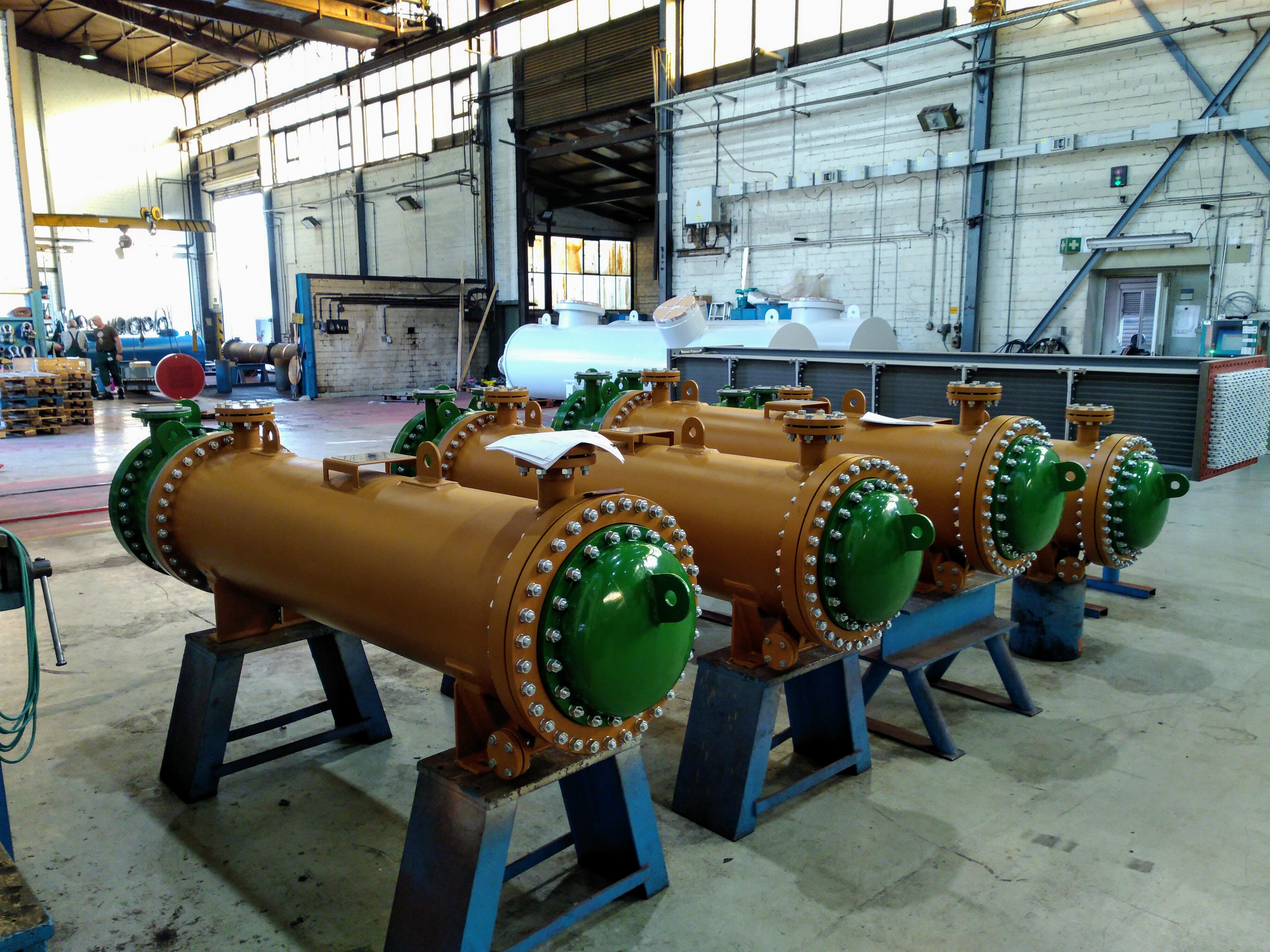
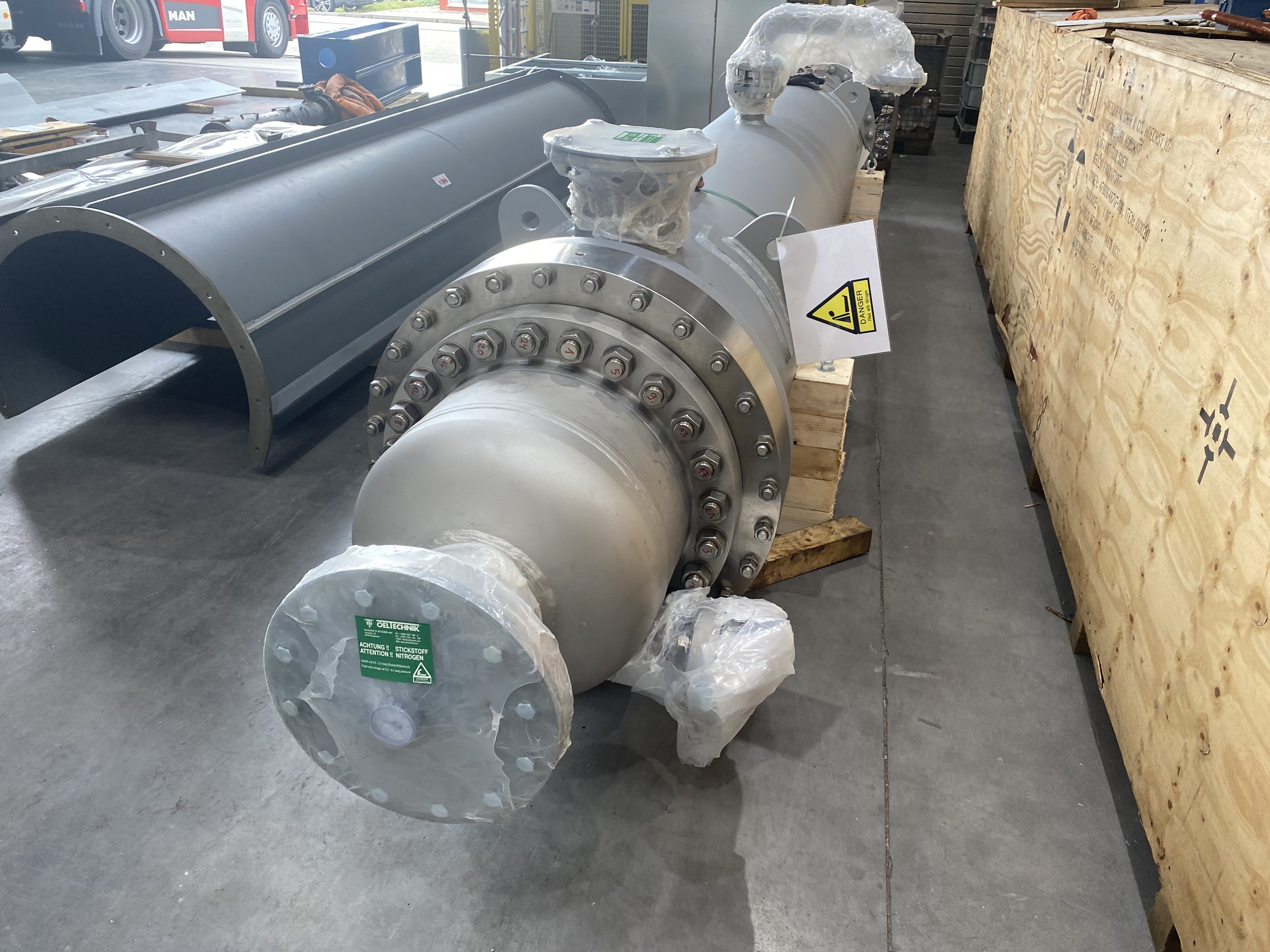
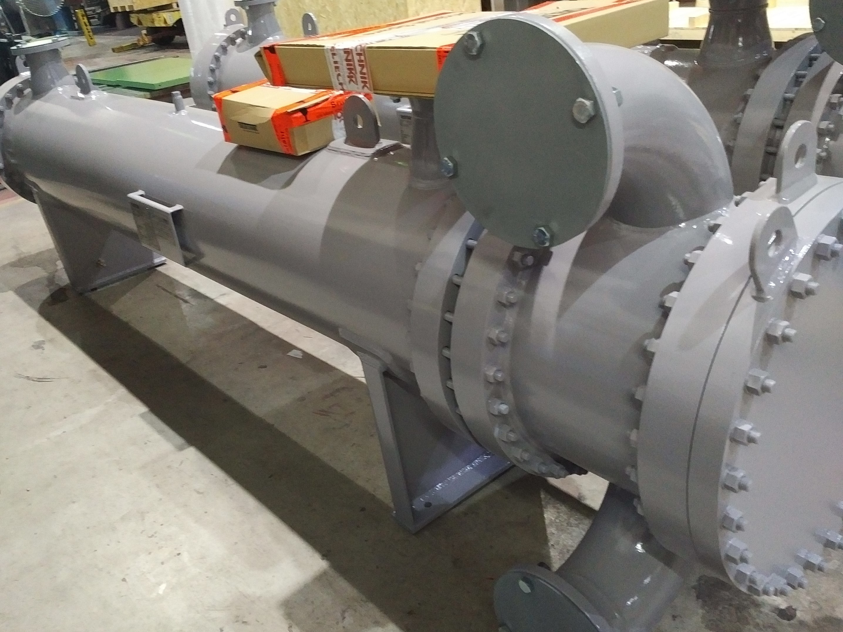
OELTECHNIK has developed, tested and continuously improved its shell & tube product program in response to the challenges of the industry. The in-house developed software is based on recognized literature such as VDI Wärmeatlas and HEI. It has been checked against actual test performance of our equipment. OELTECNIK has always taken challenges to explore further design options for shell & tube heat exchangers. Shell & tube heat exchangers are rated, designed and fabricated in-house and can be supplied according to individual customer’s specifications.
OELTECHNIK's products are successfully in use worldwide. Our design and fabrication capabilities are covering all international design codes and national regulations.
Our type OK coolers are standardized from 100 mm (4”) to 400 mm (16”) in shell diameter. Typically, oil is on the shell side and water on the tube side. For every application the coolers are individually check-rated with our thermal rating programs. For higher flow rates custom tailored designs are prevailing. Certainly, the OK type shell & tube heat exchanger can be used for other liquid to liquid applications.
The type LK indicates that one fluid is gaseous or has major gas components. Together with our customer we decide whether the gaseous fluid is on shell or tube side. Factors like design pressure, desired nozzle location, aggressiveness of fluids, desired material combination, thermal performance and allowable pressure drop influence the decision about fluid location.
OELTECHNIK will assist you in making the most economical selection under consideration and evaluation of all parameters.
Capabilities / Range of application:
| Design pressure: | 2 - 250 barg | 29 - 3625 psig |
| Design temperature: | -25 - 350 °C | -13 - 662 °F |
| Shell diameter: | 80 - 4000 mm | 3 - 157 inch |
| Maximum weight: | 100 t |
Typical fluids:
| Shell side: | Oil, water, glycol, water glycol solutions, other liquids, wet gases with separators |
| Tube side: | Water, glycol, water glycol solutions, dry gases under high pressure, wet gases with separator in down-stream |
Material combinations:
| Tubes: | Bare tubes or low-fin tubes made of: 90/10 CuNi, 70/30 CuNi, Admirality, 304 SS, 316 SS, Duplex, Super Duplex, Titanium and all other commercial available materials |
| Tube sheets: | Carbon steel, 90/10 CuNi, 70/30 CuNi, solid, cladded, CuZn 38 SnAl, Stainless steel, Duplex, Titanium, and all other commercial available plate materials |
| Channels: | Carbon steel, Stainless steel, castings in iron and copper alloys |
| Shell side: | Carbon steel, Stainless steel |
TEMA:
OELTECHNIK designs and fabricates shell and tube heat exchangers according to the recommended good manufacturing practice of TEMA (Standard of the Tubular Heat Exchanger Manufacturing Association).
References


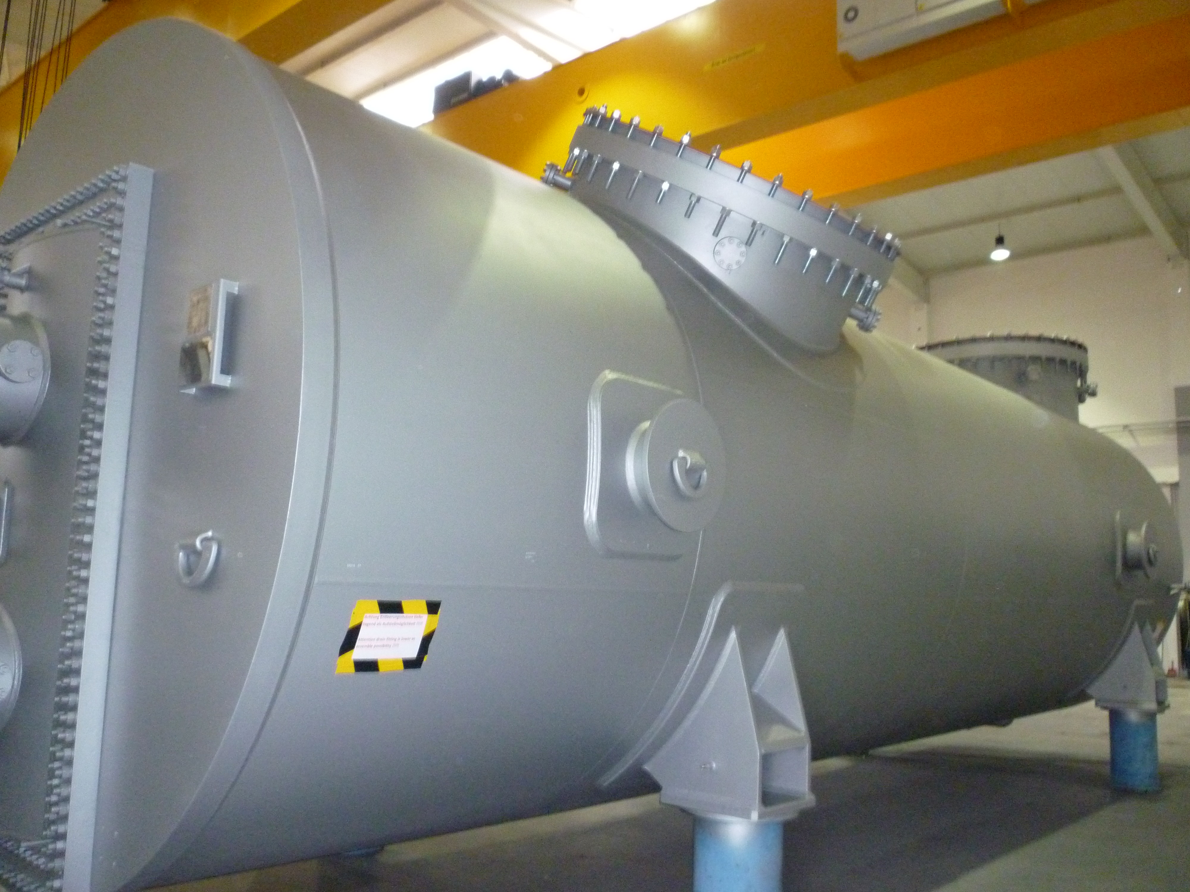
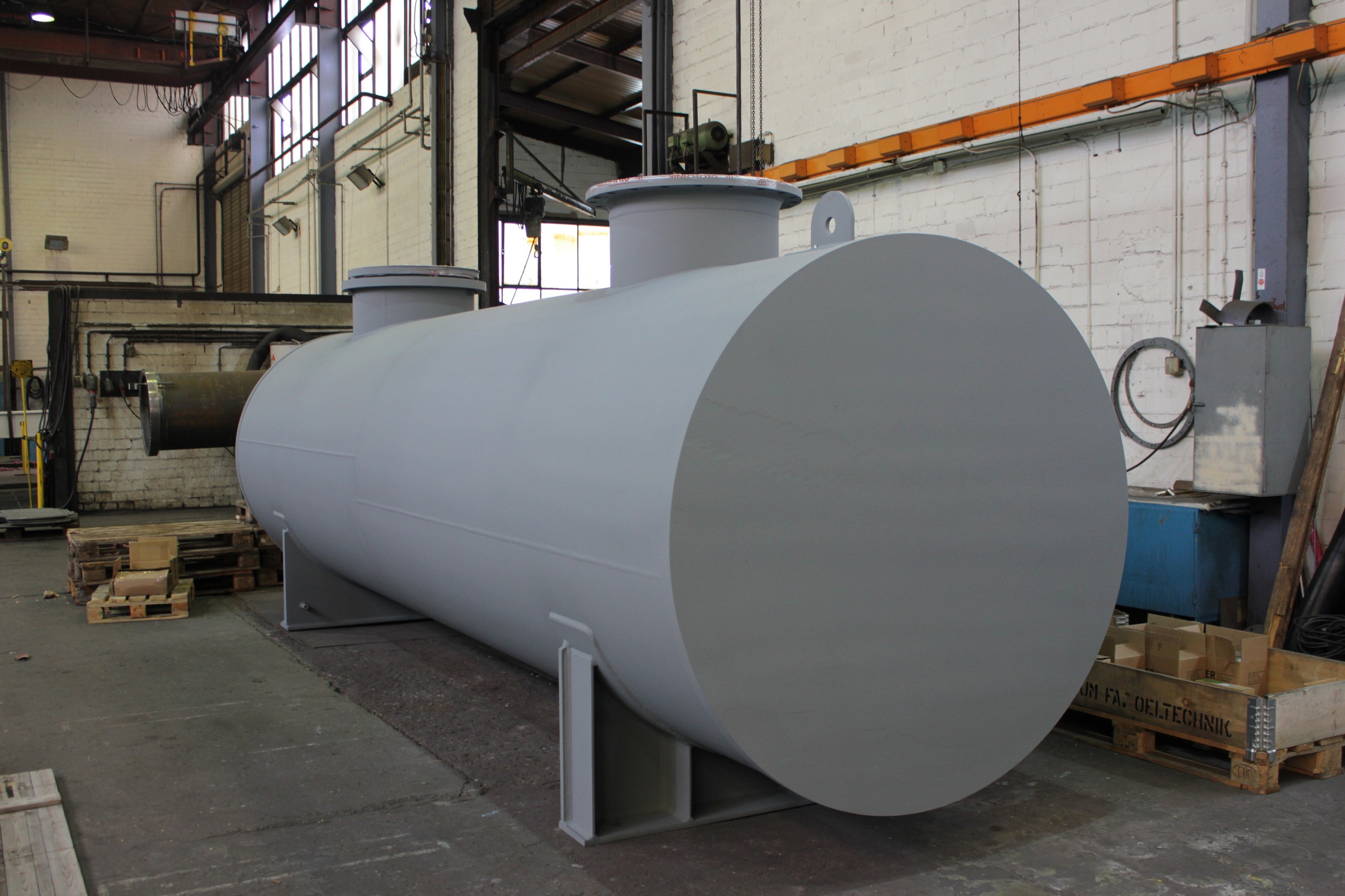
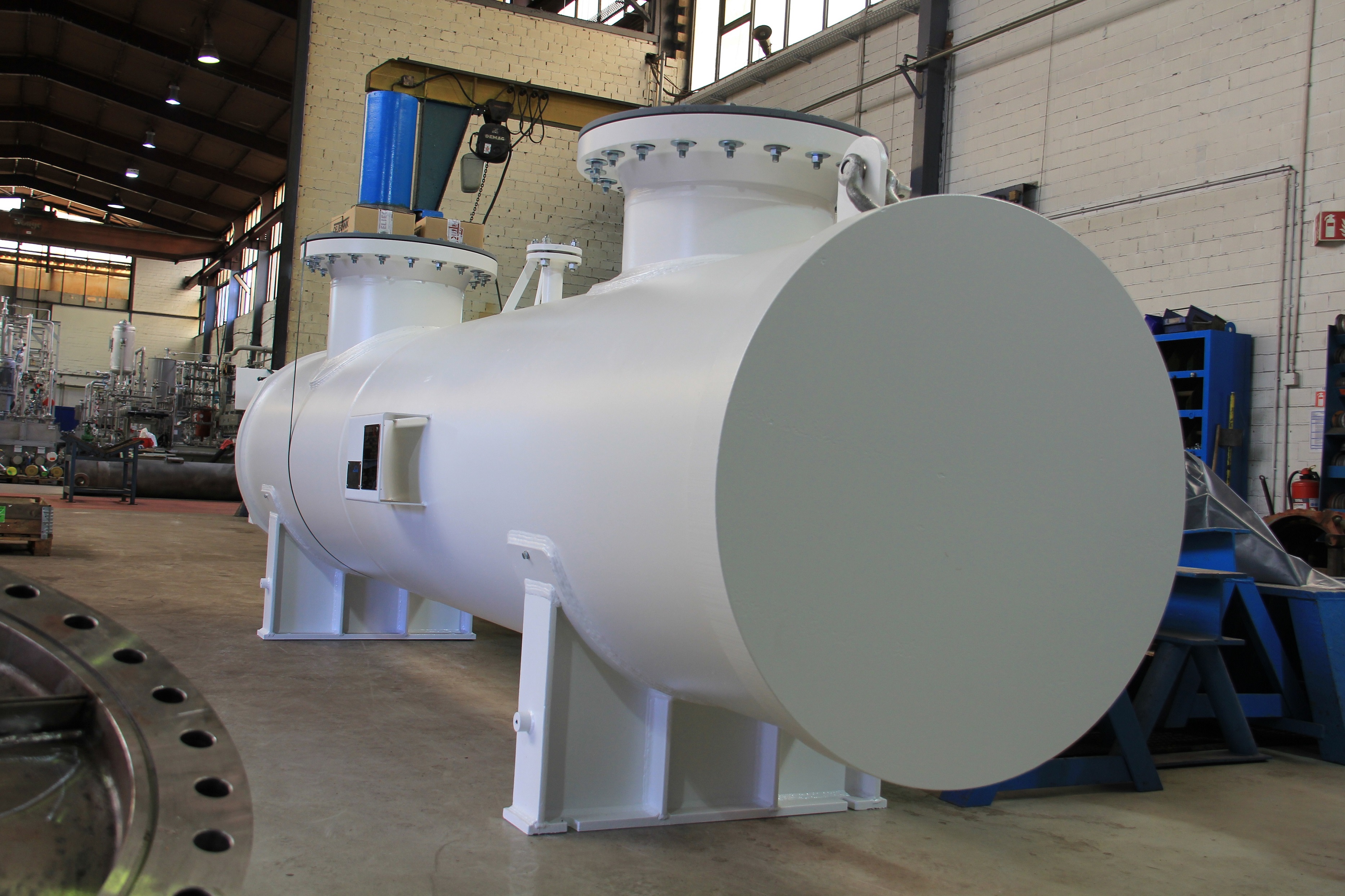
Surface condensing systems
Design parameters
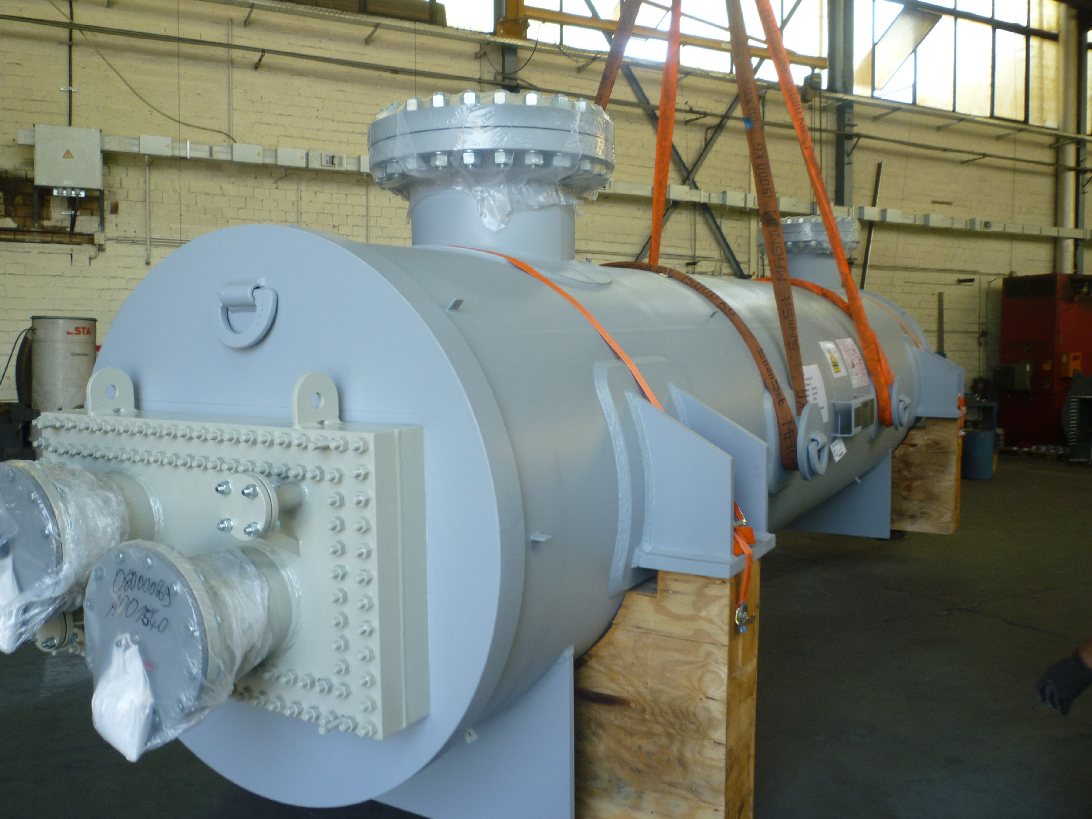
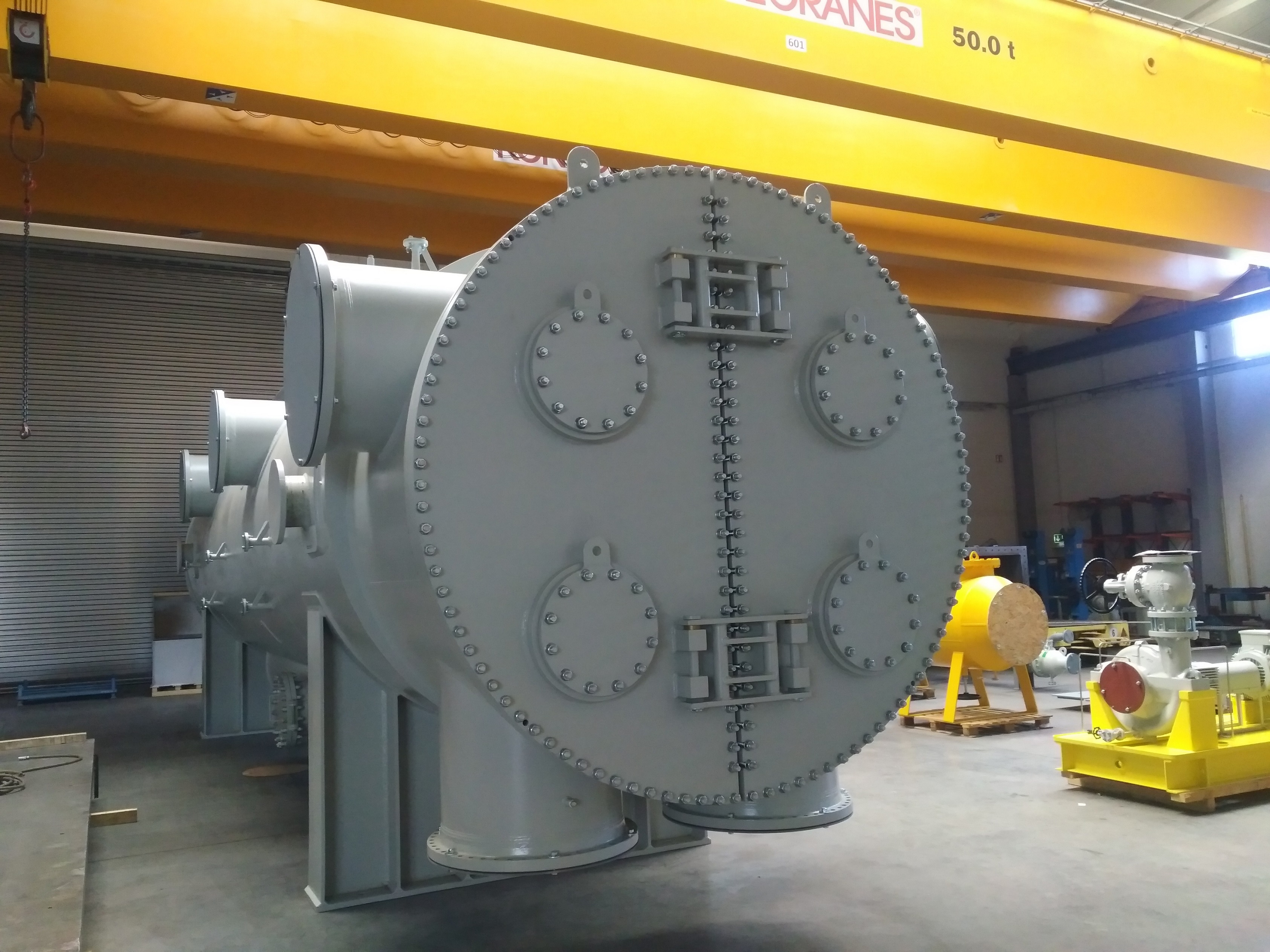
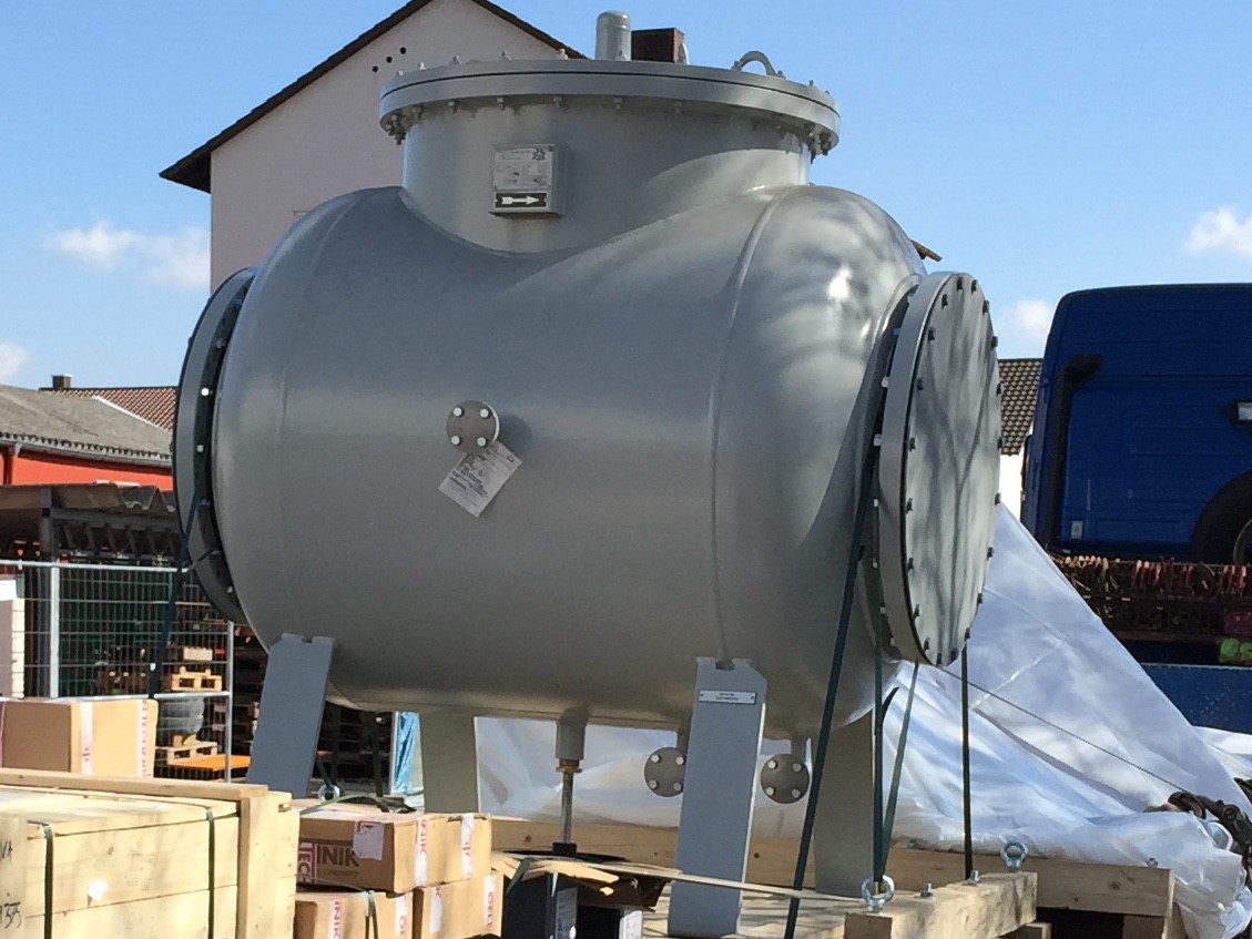
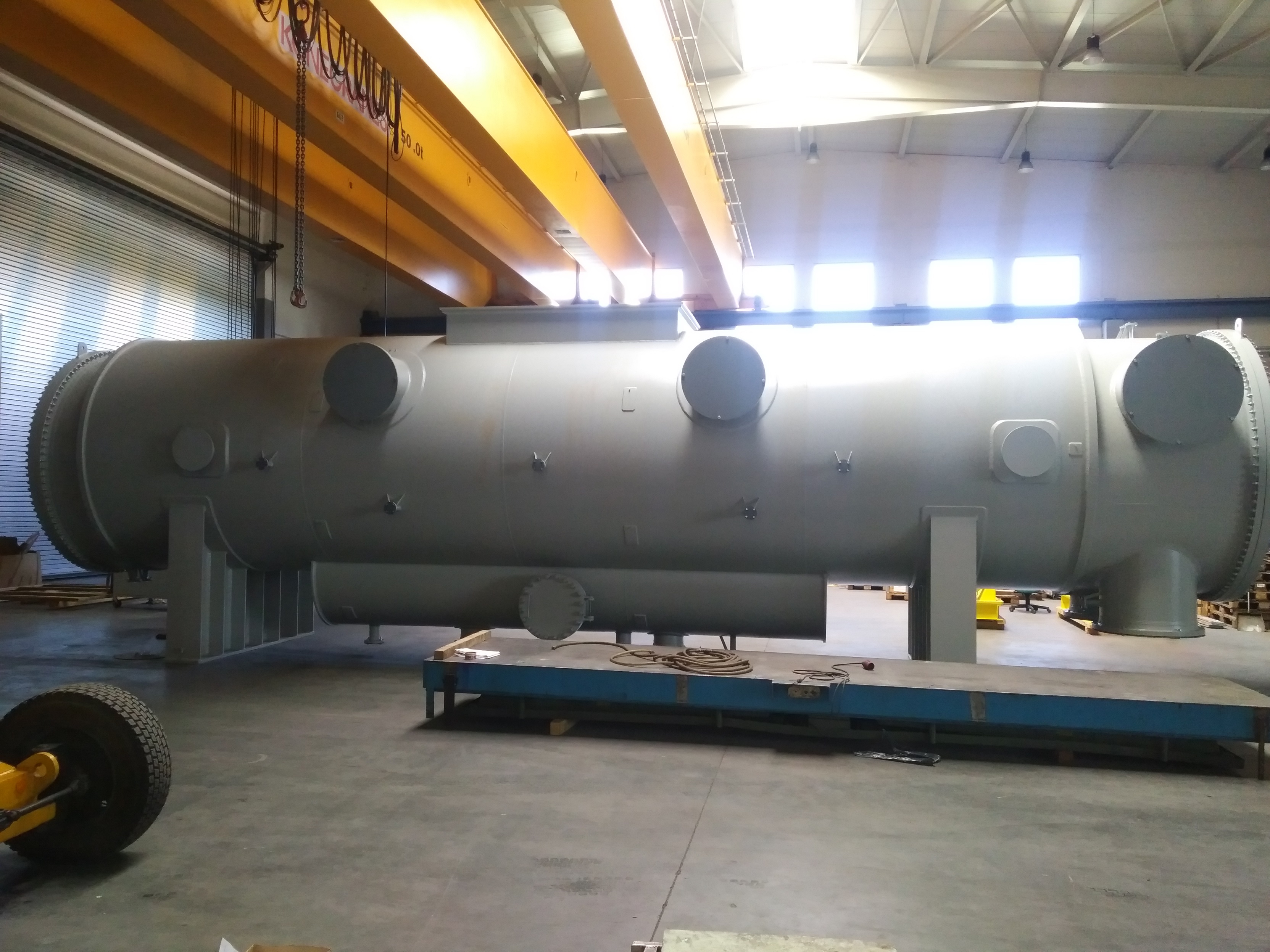
OELTECHNIK has designed, engineered, tested and continuously improved its surface condenser product in response to the needs of the turbo machinery equipment manufacture.
OELTECHNIK has supplied surface condenser systems to the international market for over 30 years. Our in house rating capabilities can be checked against HEI requirements per customer request.
OELTECHNIK´s surface condensers are in use worldwide. Our design and manufacturing capabilities are covering all international design codes and national regulations. As the condenser vessel itself is considered pressure vessel, it has to be built according to Codes and regulation of the country of installation. With us you can establish a world wide standard of your product since we have the knowledge, capabilities and certified authority to build pressure vessels to all international design codes and national regulations.
Typical applications:
- Power generation industry
- Chemical industry
- Marine applications
Capabilities – Range of Application:
| Design pressure shell side: | -1 - 10 barg | -14,5 - 145 psig |
| Design pressure tube side: | -1 - 15 barg | -14,5 - 217 psig |
| Maximum diameter: | ~4000 mm | ~157 inches |
Materials:
| Tubes: | Admiralyty, 90/10 CuNi, 70/30 CuNi, 304 SS, 316 SS, Duplex, Titanium, Carbon steel tube |
| Sheets: | Carbon steel, CS epoxy baked coated, Stainless steel, 90/10 CuNi solid and cladded |
| Shell side: | Carbon steel, Stainless steel |
WKG surface condenser systems include:
- Surface condenser
- Hotwell
- Transition piece
- Flash box
- Condensate pumps
- Safety valve steam side
- Condensate level control
- System control instrumentation (LIC, LI, LET)
- Evacuation unit, including: steam ejector or vacuum pump, intercondenser, piping
References


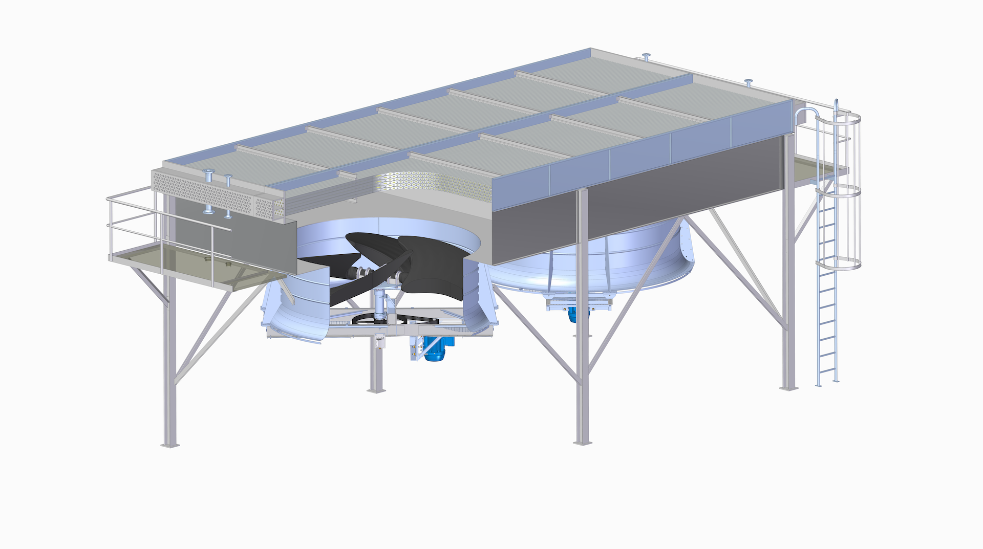
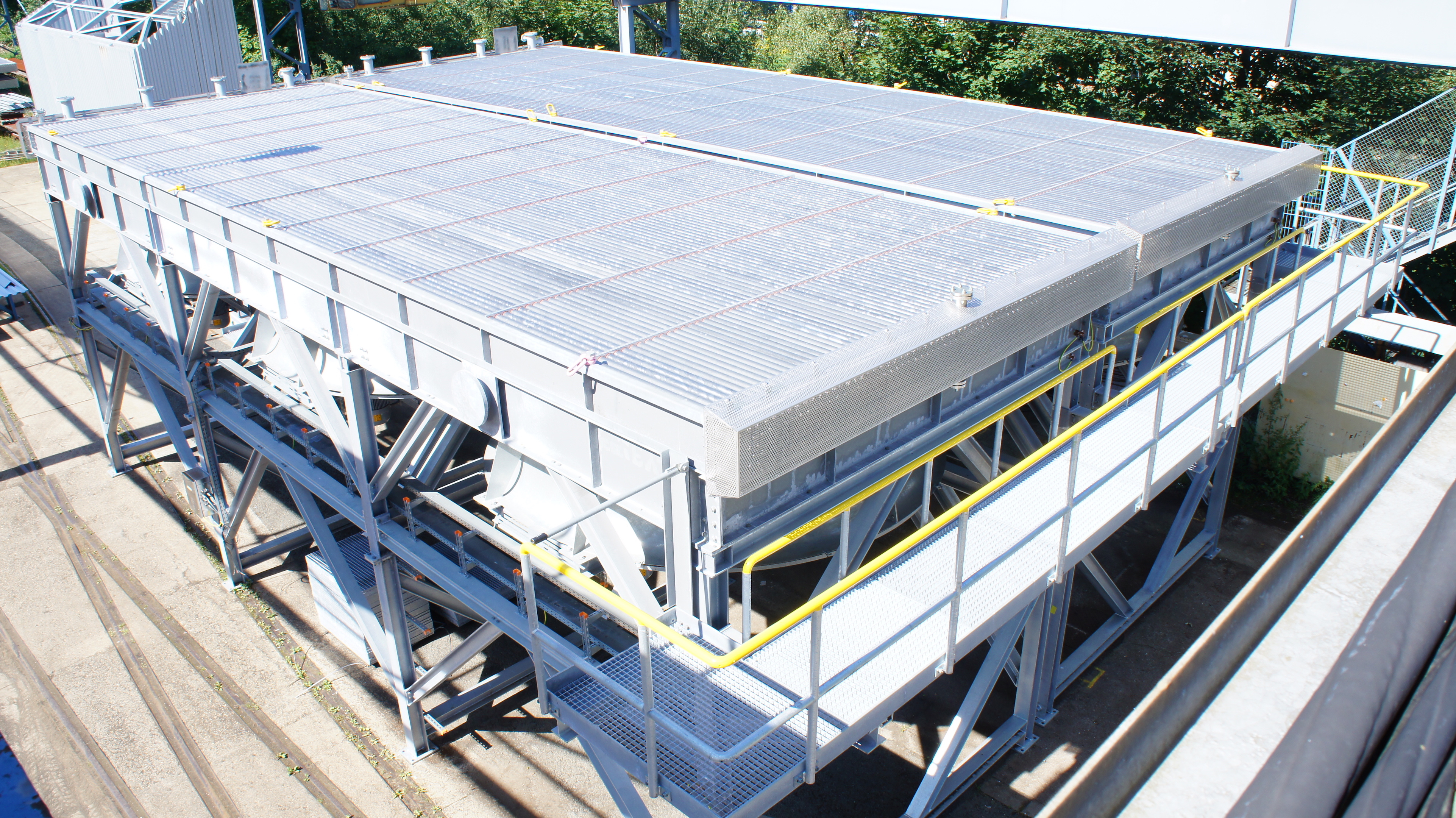
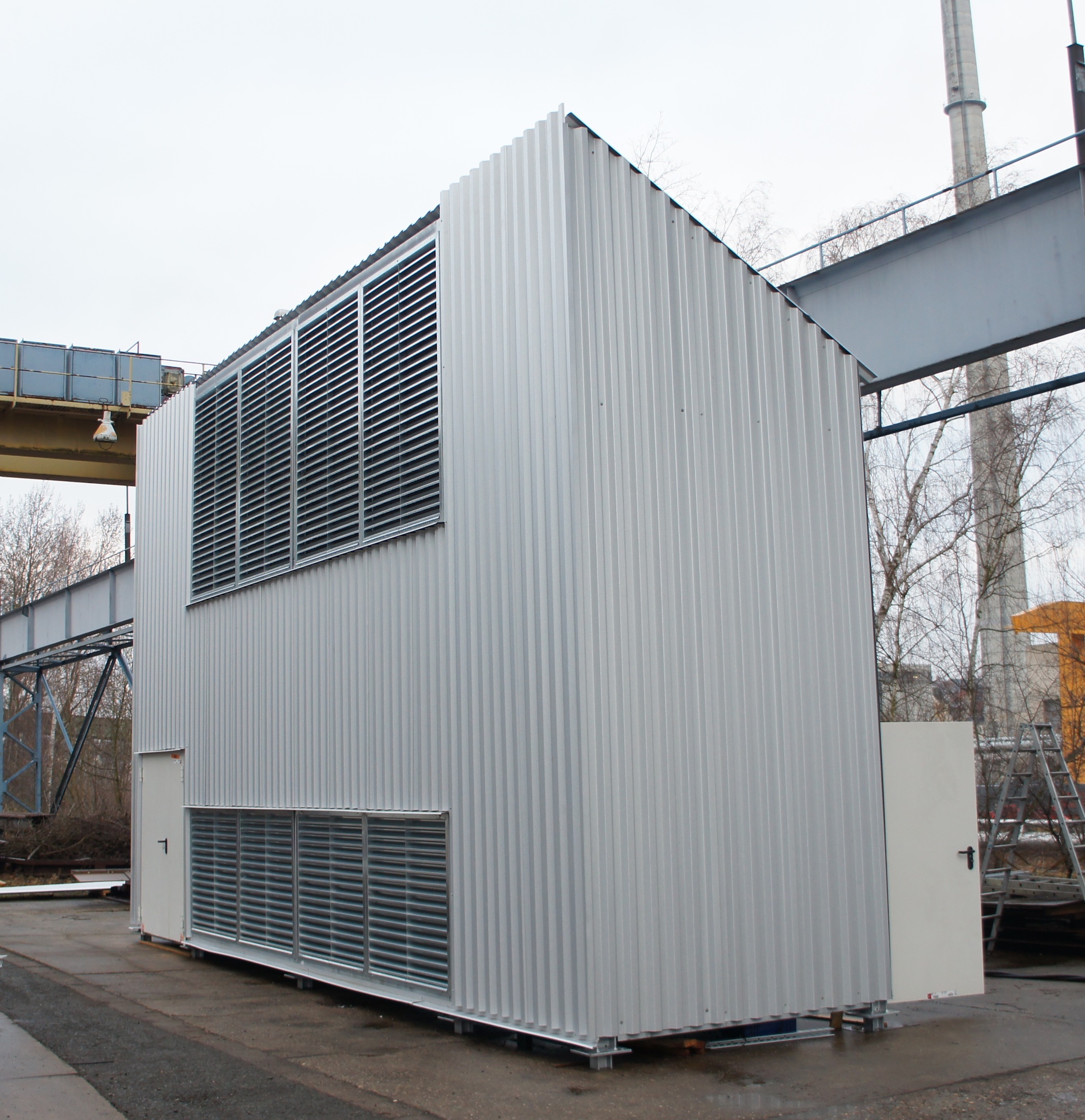
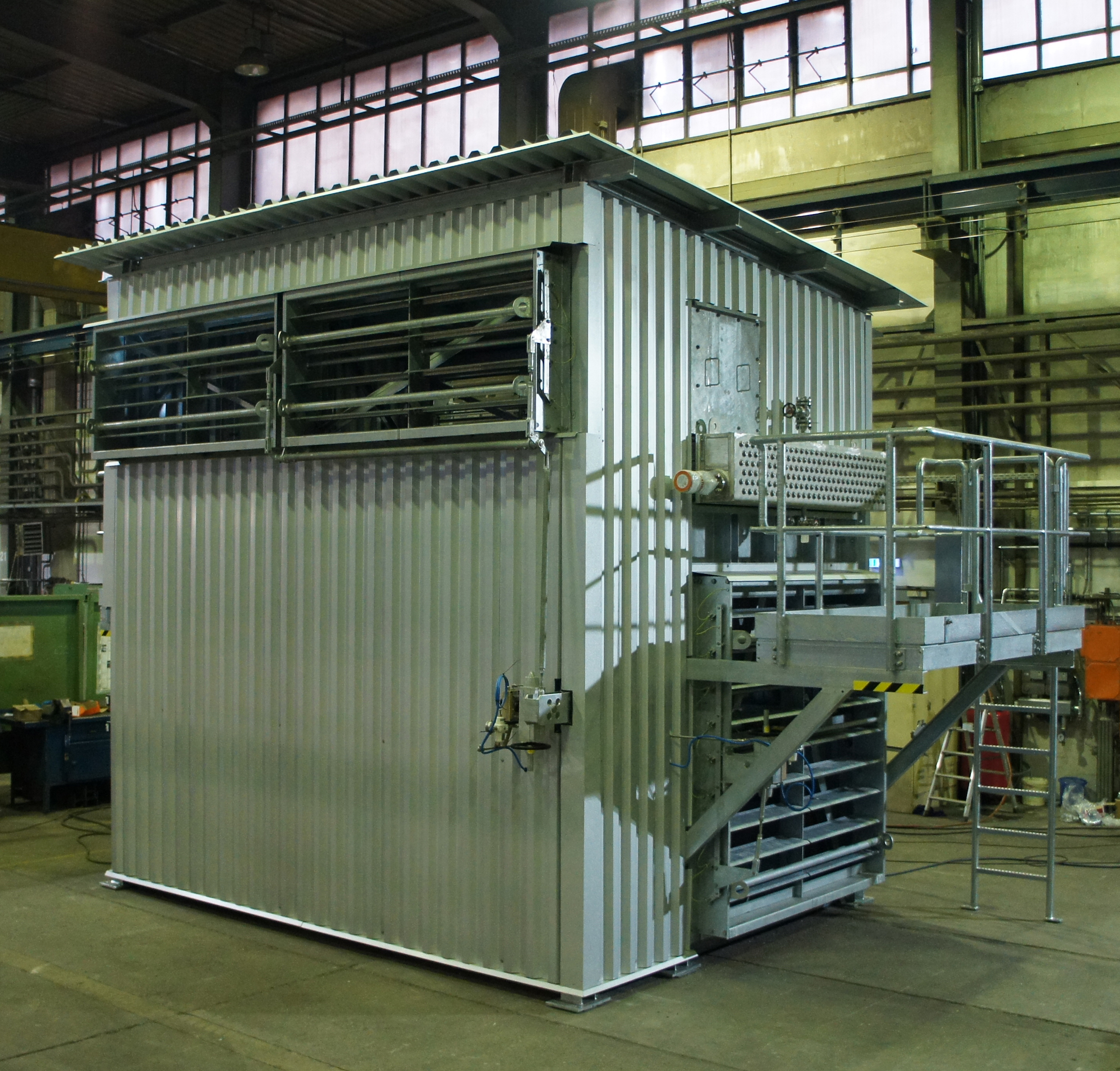
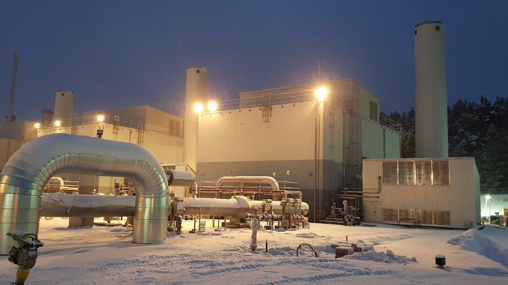
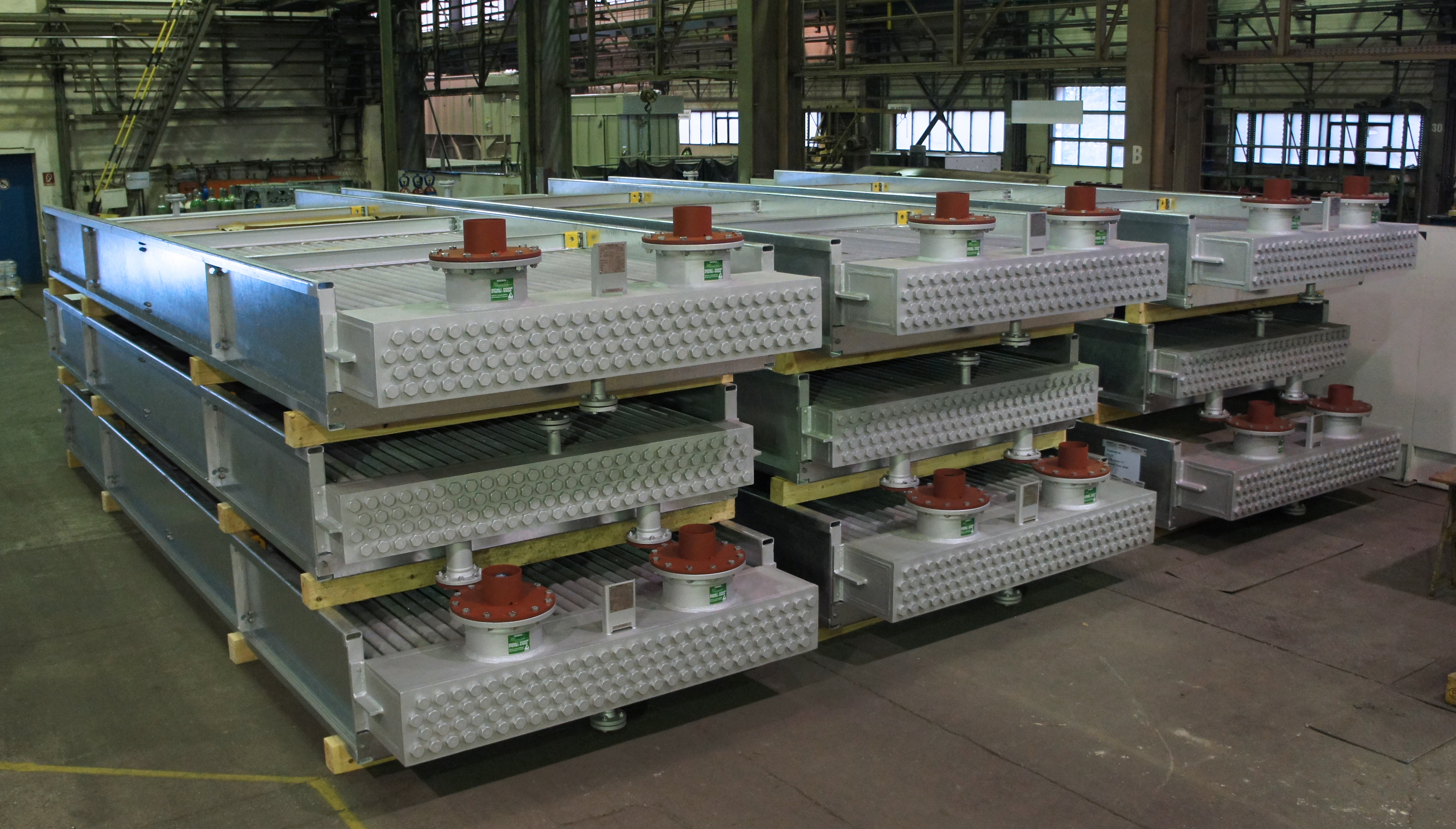
Air Cooled Heat Exchangers / Fin Fan Coolers
Design parameters
|
|
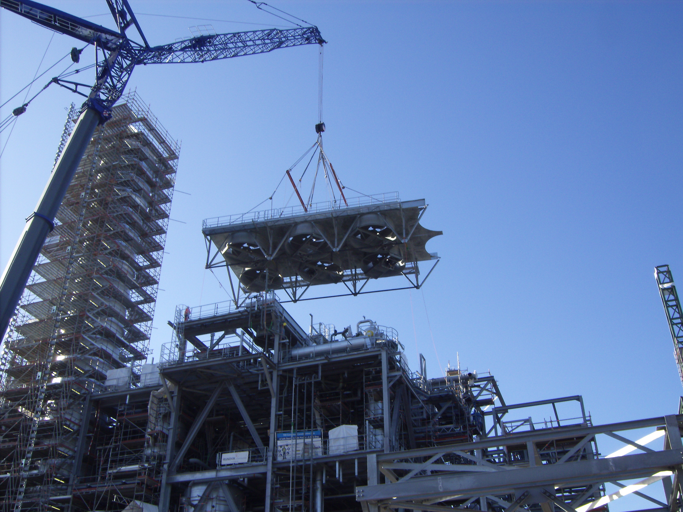
heat exchanger weight: up to 30t |
Features:
- Air-cooled heat exchanger
- Rectangular bundle design with finned or bare tubes
- Fluid: any gas or liquid
- Used in: refineries, chemical plants, ...
- Technological steel construction
- API 661 Standard or customer’s specifications
- Produced according to all national and international regulations
- Nationally and internationally certified (China, Poland, Hungary,…)
Material combinations:
| Fluid side material: | CS, SS, CuNi, ... |
| Fin material: | Al, Cu, CS, SS, ... |
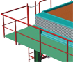
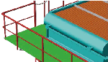
Overview:
 |
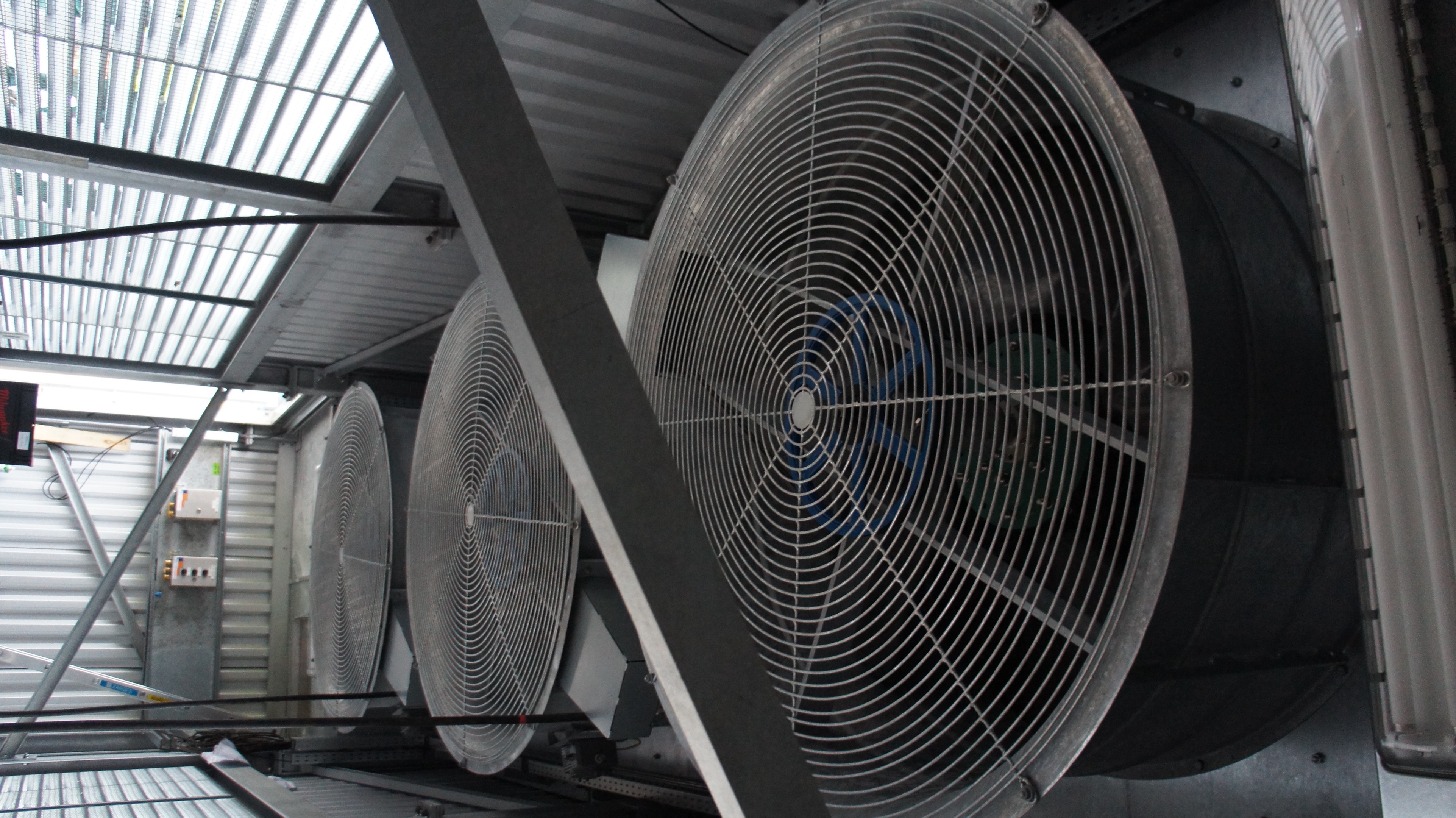
This arrangement, where air is pushed across the bundle, meets API 661 "forced draft".
|
 |
This arrangement, where air is pulled through the bundle, meets API 661 "induced draft".
|
 |
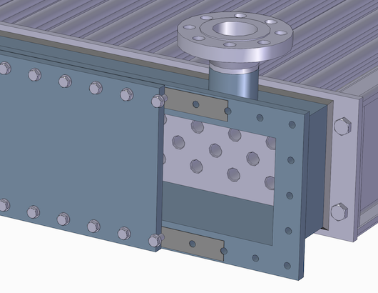
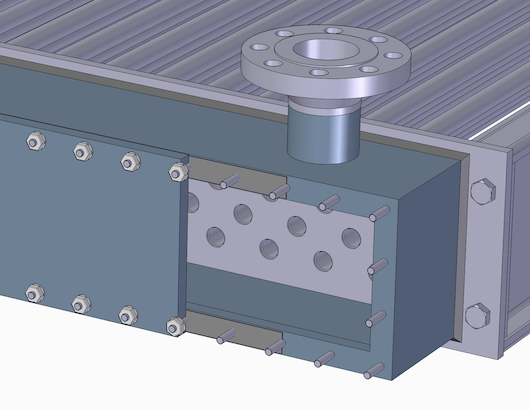
This header design, with a flanged cover-plate, meets API 661 "removable cover-plate header".
|
|
|
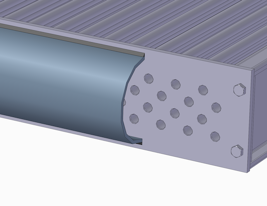
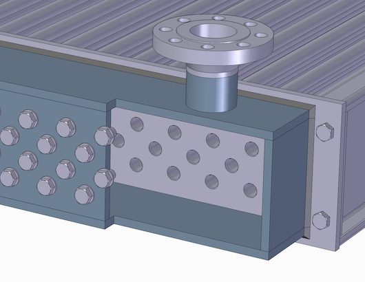
This header design, with a shoulder plug opposite to each tube end, meets API 661 "plug header".
|
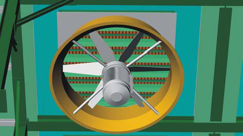 |
The axial fan with driver
|
|
|
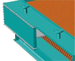
The bonnet header with a half pipe end construction. |

Header design:
| Bonnet header (welded D Type) | Removable cover-plate header | Plug header |
|---|---|---|
 |
|
|
| Design range: standard: up to 25 bar, costumized design possible up to 100 bar | Design range: up to 40 bar, customized design possible with higher pressure | Design range: up to 250 bar |
References


Please contact us
We will be glad to advise you
Address
Gesellschaft für OELTECHNIK mbH
Lessingstr. 32
68753 Waghäusel
Deutschland
Telefon: +49 (0) 7254 981 0
Telefax: +49 (0) 7254 981 105
E-Mail: service@oeltechnik.de